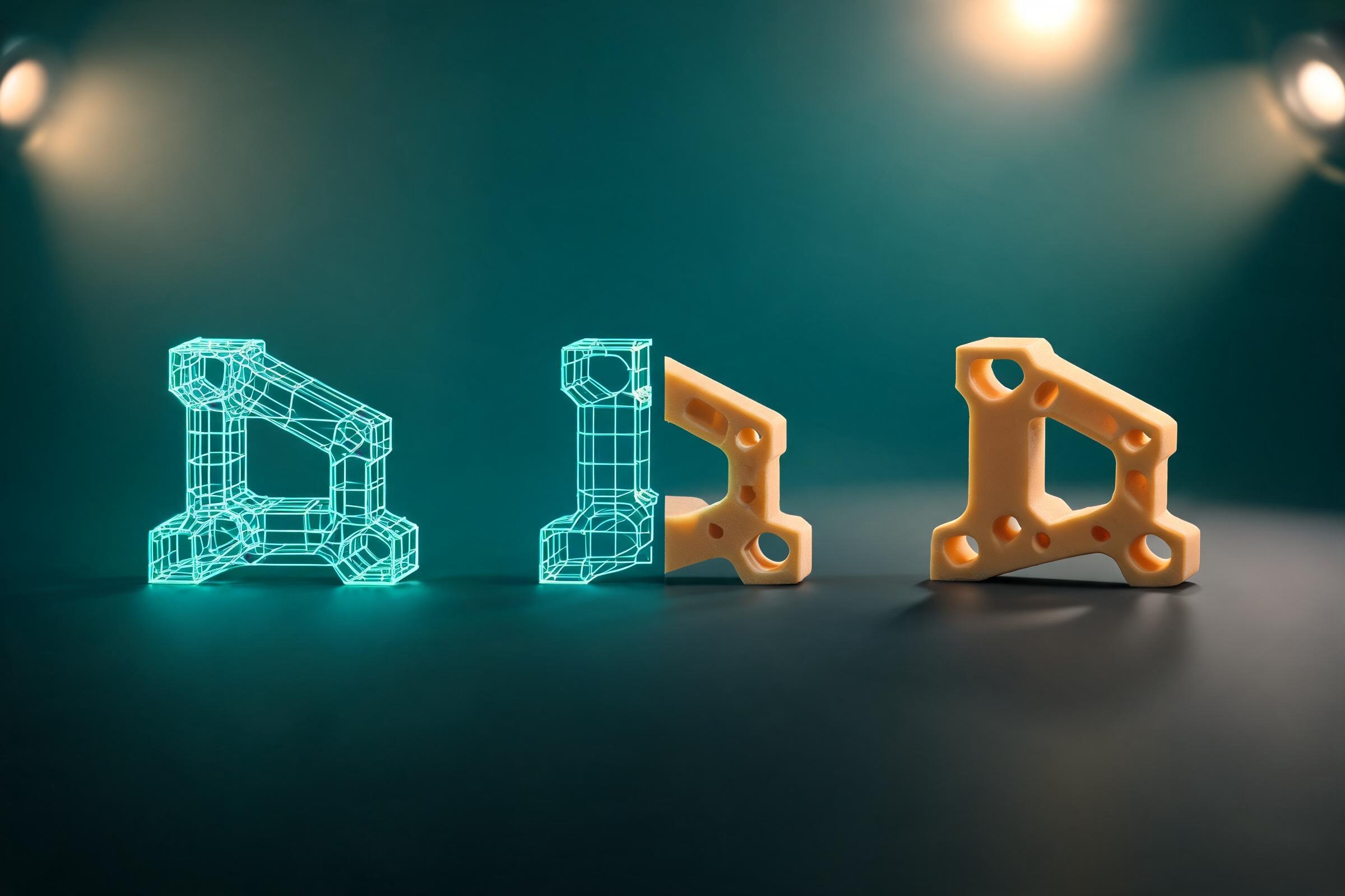
Key takeaways
- A 3D printing prototype is a physical test part made from a digital model to answer a specific design question. AI can accelerate concept geometry, but the file still needs dimensional reconstruction, watertight topology, wall and clearance checks, process-aware orientation, slicing, and a measured test print before it is production-ready.
- Quotable summary: AI can accelerate 3D prototype ideation, but print readiness comes from controlled geometry, process-specific slicing, and measured physical validation.
Direct answer: how to make a 3D printing prototype
A 3D printing prototype is most useful when it tests one explicit risk: fit, form, motion, assembly, ergonomics, or manufacturability. Start with a measurable requirement, create or generate a digital concept, rebuild critical dimensions in CAD or a controlled mesh workflow, validate print readiness, slice with the intended process, print the smallest useful test, measure the result, and revise. AI can shorten ideation and rough-shape work, but it does not replace engineering dimensions, process selection, slicer inspection, or physical validation.
Define the prototype question before modeling
“Make a prototype” is too vague. A visual appearance model may only need the right silhouette and surface language. A snap-fit test must preserve mating dimensions, insertion direction, flexing length, clearance, and expected cycles. A handheld enclosure may need separate tests for grip, button reach, board clearance, fastener access, and thermal space. Write the decision the print must support, the acceptance measurement, and what the prototype is not intended to prove.
Choose fidelity deliberately. A low-fidelity volume study can be hollow, simplified, and printed quickly. A fit-check should include interfaces but may omit cosmetic texture. A functional prototype needs material and orientation choices that resemble the expected loading, while still being understood as a test rather than certified production hardware. This framing prevents teams from spending hours polishing geometry that cannot answer the main question.
For example, if the uncertainty is whether a sensor board fits, print only the enclosure region around mounts, connectors, and cable bends. If the uncertainty is grip comfort, create three shells with different curvature and label each version. If the uncertainty is a hinge, isolate the hinge and its stops. Every iteration should produce an observation that changes or confirms a design decision.
Concept-to-print workflow
- Write constraints. Record target size, interfaces, forbidden regions, expected force, desired material behavior, available printer, and the one question this iteration must answer.
- Create the concept. Sketch, model, scan, or use AI-assisted 3D generation for rough form exploration. Treat generated geometry as a draft, not a dimensionally authoritative part.
- Reconstruct critical geometry. In CAD, define datums, dimensions, wall thicknesses, holes, clearances, and feature relationships. In a mesh workflow, establish scale, watertight volume, normals, and editable topology.
- Select process and material. Fused filament fabrication, vat photopolymerization, powder-bed processes, and other methods have different support, feature, strength, finish, and cost behavior.
- Validate the file. Check connected components, manifold edges, self-intersections, inverted normals, minimum features, trapped volumes, intended tolerances, and export units.
- Slice and inspect. Use the actual printer/material profile. Review every layer near thin walls, holes, bridges, interfaces, and support contact. Estimate time and material only as profile-specific planning values.
- Print the smallest useful experiment. Use coupons, partial sections, or one critical mechanism before a complete enclosure or assembly.
- Measure and document. Compare the physical result with acceptance criteria, record orientation and settings, then update the editable master rather than patching only the STL.
This loop is intentionally evidence-driven. A beautiful render cannot show layer adhesion, dimensional drift, warping, support scars, or how a joint feels. The prototype is a measurement instrument; the output should be a decision and revision record, not merely a photographed object.
AI generation versus CAD for prototype work
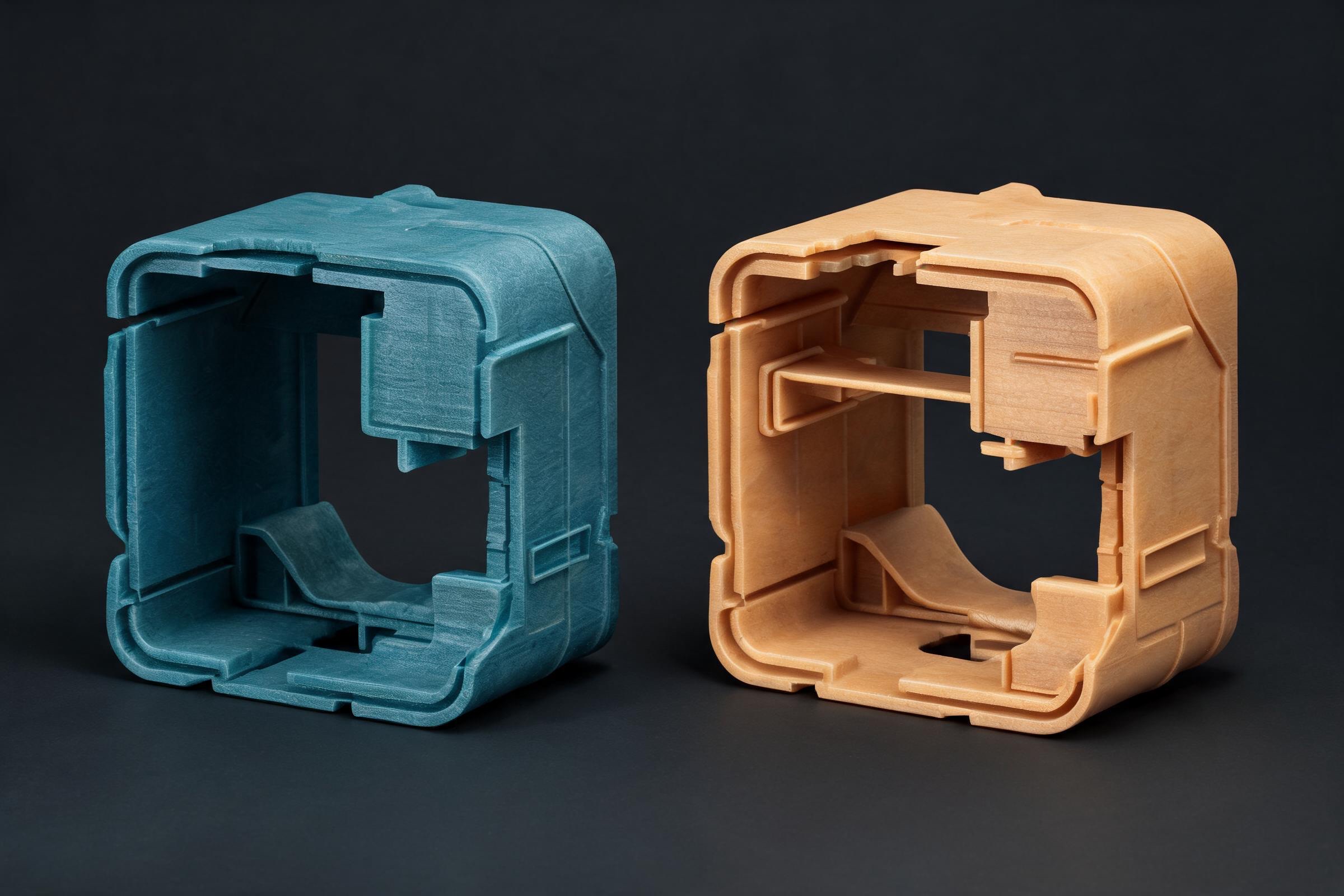
The following comparison is a decision matrix for choosing where AI-assisted generation or parametric CAD fits in a prototype workflow.
Early form exploration
- AI-assisted 3D generation: Fast at producing shape directions from text or references.
- Parametric CAD: Slower when requirements are unsettled.
- Practical decision: Use AI or sketching to expand options.
Exact dimensions and interfaces
- AI-assisted 3D generation: Generated topology may not preserve engineering intent.
- Parametric CAD: Dimensions, constraints, and feature history are explicit.
- Practical decision: Use CAD for mounts, holes, fits, and revisions.
Organic surfaces
- AI-assisted 3D generation: Often useful for a rough sculptural starting point.
- Parametric CAD: Possible but not always efficient.
- Practical decision: Generate or sculpt, then rebuild critical zones.
Variant generation
- AI-assisted 3D generation: Useful for visual diversity.
- Parametric CAD: Strong for controlled parameter families.
- Practical decision: Choose based on whether variation is aesthetic or dimensional.
Print readiness
- AI-assisted 3D generation: Cannot be assumed from appearance.
- Parametric CAD: Solid modeling helps but still needs process checks.
- Practical decision: Validate both in mesh tools and the target slicer.
Change traceability
- AI-assisted 3D generation: A prompt and output may not encode why a feature exists.
- Parametric CAD: Feature history can preserve design relationships.
- Practical decision: Keep a revisioned editable master and test log.
A hybrid workflow is usually stronger than arguing that one method replaces the other. Use generated form where ambiguity is valuable, then move accepted geometry into a controllable model. Preserve the generated reference, conversion steps, scale decisions, and any remodeled surfaces. If decimation or automatic repair changes a mating face, return to the source model and repair intentionally.
Print-readiness checklist
- [ ] The model is at the intended physical dimensions and units are documented.
- [ ] Every printed shell has process-appropriate wall thickness; decorative single surfaces have been given physical thickness where required.
- [ ] The mesh is watertight where the process expects a closed volume, with no accidental internal faces, duplicate shells, or inverted normals.
- [ ] Holes, pins, clips, and sliding interfaces include testable clearance rather than ideal zero-clearance dimensions.
- [ ] Small text, ribs, and gaps are large enough for the chosen nozzle, exposure, powder, or service specification.
- [ ] Orientation reflects surface priority, support access, anisotropic strength, and build stability.
- [ ] Supports can be removed without destroying critical surfaces or trapping material.
- [ ] The slicer layer preview shows continuous intended material around all critical features.
- [ ] A revision name links the source model, export, slicer profile, and measured result.
- [ ] Safety-critical, medical, food-contact, pressure, electrical, or load-bearing use has appropriate specialist review.
Do not convert this checklist into universal millimeter limits. Printer capability, material, process, calibration, geometry, and service-provider rules determine practical thresholds. A value copied from another machine is only a hypothesis until tested under the intended conditions.
Failure conditions and diagnostic response
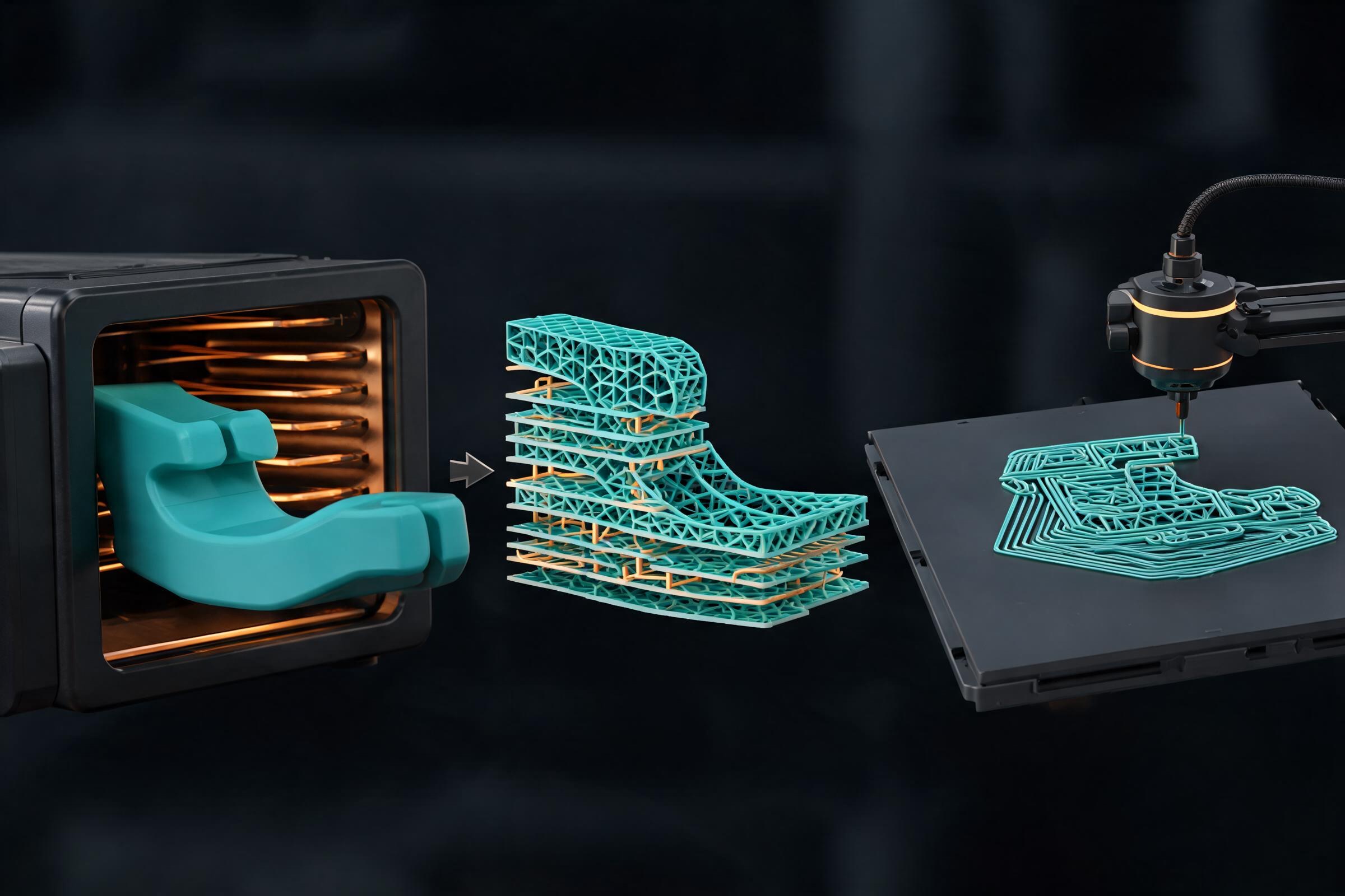
The slicer deletes a wall or pin. The feature may be thinner than the toolpath or exposure strategy can resolve, or triangulation may have collapsed it. Increase the feature intentionally, use an appropriate process, and inspect the relevant layers again.
The part imports at the wrong size. STL is not a reliable carrier of unit intent. Confirm dimensions in the source model and slicer, document the expected unit, and consider a format or handoff that preserves more metadata when supported.
A repaired mesh looks printable but dimensions changed. Automated repair closes gaps by inference. Compare against the source and measure critical features after repair. Rebuild functional faces instead of accepting an opaque fill.
A snap-fit breaks. The cause may include material brittleness, layer orientation, notch geometry, excessive interference, print defects, or unrealistic use. Isolate the clip, print clearance and orientation variants, and avoid declaring the entire design invalid from one uncontrolled sample.
The prototype warps or detaches. Geometry, material condition, thermal environment, bed preparation, build orientation, and profile all matter. Record the actual conditions and change one factor per trial when possible.
Turning a prototype into a reliable decision
Measure what the prototype was built to test. Calipers can verify selected dimensions, but functional gauges, mating components, force tests, photos, and user observations may be more meaningful. Record sample count; one successful print does not characterize process variation. If a feature is close to the limit, print it in several positions and orientations or use a dedicated tolerance coupon.
Separate design findings from process findings. “The connector collides with the wall” is a design issue. “The first layer widened the opening” may be a process issue. “The clip fractures only when layers run across the hinge” connects design and orientation. This distinction makes revisions reusable instead of accumulating arbitrary offsets.
A production candidate needs more than a prototype. It may require material traceability, process qualification, repeatability studies, inspection planning, environmental testing, and regulatory review. The prototype workflow here helps reduce uncertainty; it does not certify the final part.
Continue the print-preparation workflow
Use the AI 3D printing model editor to move from a concept toward editable geometry. Before export, compare FBX, glTF, OBJ, and STL handoff choices, run mesh cleanup and repair, reduce unnecessarily dense geometry with the free 3D polygon reducer, and finish with the scale, slicing, and support checklist. These tools support preparation; they do not certify a part for a specific printer, material, load, or regulated use.
Sources and freshness
- ISO/ASTM 52900:2021 — Additive manufacturing terminology, edition published 2021; checked 2026-08-04 for the process definition and category vocabulary.
- NIST — Additive Manufacturing, checked 2026-08-04 for measurement, process control, and qualification context.
- U.S. Department of Energy — Additive Manufacturing, checked 2026-08-04 for manufacturing context and the layerwise-build explanation.
- U.S. FDA — 3D Printing of Medical Devices, checked 2026-08-04 for regulated-use boundaries.
A concise, citable summary is: 3D printing is a family of additive manufacturing processes that makes physical objects from digital model data, usually by building material layer by layer; the exact material, bonding method, accuracy, and post-processing depend on the selected process. Standards and vendor guidance change, so verify the current machine, material, and service-bureau documentation before committing a production part.
Frequently Asked Questions
What is the fastest useful 3D printing prototype?
The fastest useful prototype is the smallest print that answers the highest-risk question. A partial enclosure, connector section, hinge coupon, or three labeled grip variants often teaches more than a complete polished object while reducing print time, material use, and the number of uncontrolled variables.
Should I use AI or CAD for a 3D printing prototype?
Use AI-assisted generation for ambiguous form exploration and CAD for dimensions, interfaces, constraints, and repeatable revisions. A hybrid workflow is often strongest: explore shapes quickly, then reconstruct or control every surface and feature that affects fit, function, safety, inspection, or manufacturing.
Why can an AI-generated 3D model fail in a slicer?
A generated model can look complete while containing open boundaries, overlapping shells, inverted normals, self-intersections, zero-thickness surfaces, tiny disconnected components, or inconsistent scale. Inspect the actual mesh and layer preview, then rebuild functional geometry instead of assuming an automatic repair preserved the intended shape.
How should I validate tolerances in a printed prototype?
Start with the printer, material, orientation, and mating parts you actually plan to use. Print a small clearance or fit coupon around the relevant dimensions, measure more than one sample, record settings and environmental conditions, and update the editable master from evidence rather than applying an undocumented global offset.
What should I record after each prototype iteration?
Record the design revision, export format and units, printer and material, orientation, slicer profile, build conditions, measured dimensions, observed failure location, photos, and the decision made. This trace separates geometry changes from process changes and makes the next test reproducible instead of relying on memory.