Key takeaways
- 3D printing works by turning a digital model into process-specific machine instructions, then selectively adding or bonding material to create successive cross-sections. The complete workflow includes requirements, model validation, orientation, slicing, setup, building, post-processing, and inspection.
- Quotable summary: A 3D printer does not simply copy a model; it executes a prepared manufacturing process whose geometry, material, settings, and inspection all affect the result.
Direct answer: how does 3D printing work?
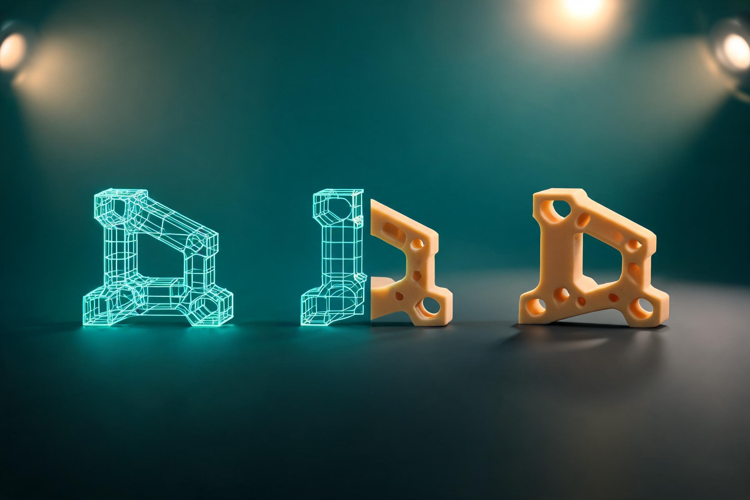
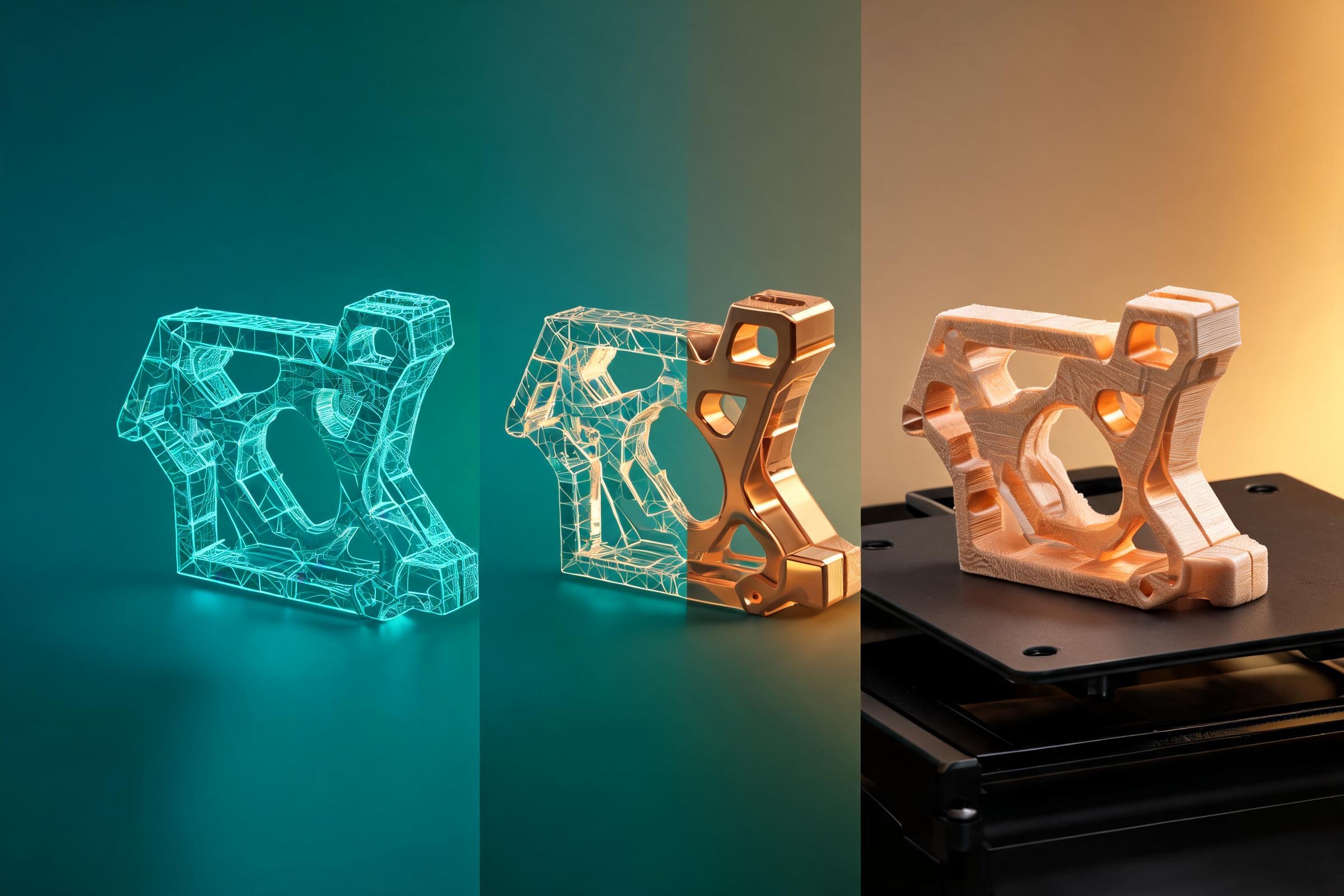
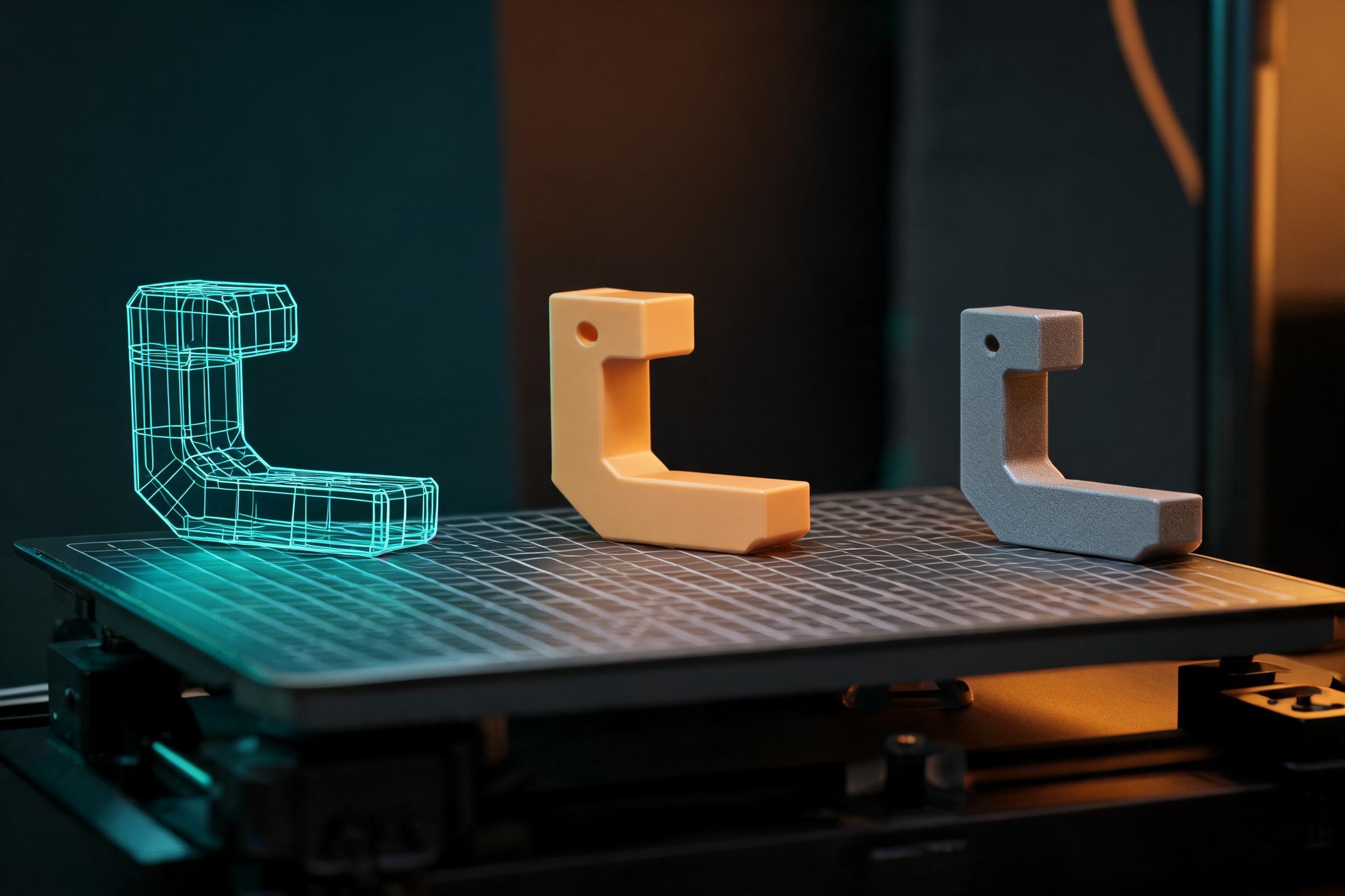
3D printing works by converting a digital 3D model into machine instructions that create the object as a sequence of cross-sections. Software checks and orients the geometry, generates layers or toolpaths, and applies process settings. The machine then deposits, cures, fuses, jets, or binds material in selected locations. After the build, the part is removed, cleaned, post-processed, and inspected. The layer-by-layer idea is shared, but hardware, materials, supports, accuracy, and finishing vary significantly by process.
The complete process at a glance
This eight-stage process map names the input, transformation, output, and most common failure at every step from requirements to inspection.
1. Requirements
- Input: Intended use and acceptance criteria.
- What happens: Define size, load, surface, tolerance, quantity, and risk.
- Output: Build brief.
- Frequent failure: Printing before knowing what must be proven.
2. Digital model
- Input: CAD, mesh, scan, or generated geometry.
- What happens: Create or reconstruct controlled geometry.
- Output: Editable master.
- Frequent failure: An attractive but dimensionally uncontrolled shape.
3. File preparation
- Input: Model and process choice.
- What happens: Repair, orient, scale, nest, and add supports.
- Output: Prepared build.
- Frequent failure: Wrong units, hidden shells, or trapped material.
4. Slicing
- Input: Prepared build and machine profile.
- What happens: Generate layers, paths, exposures, or scan strategy.
- Output: Machine instructions.
- Frequent failure: Thin features vanish or supports are inaccessible.
5. Machine setup
- Input: Instructions, material, and calibrated machine.
- What happens: Load material, prepare the platform, and verify conditions.
- Output: Ready build system.
- Frequent failure: Wrong profile, wet material, or poor calibration.
6. Build
- Input: Ready system.
- What happens: Add or bond selected material cross-section by cross-section.
- Output: As-built part.
- Frequent failure: Warping, detachment, incomplete fusion, or exposure error.
7. Post-process
- Input: As-built part.
- What happens: Remove, clean, cure, depowder, heat-treat, or machine.
- Output: Finished candidate.
- Frequent failure: Damage during support removal or incomplete cure.
8. Inspect
- Input: Finished candidate and criteria.
- What happens: Measure dimensions, function, defects, and records.
- Output: Accept, rework, or revise decision.
- Frequent failure: Judging only by appearance.
Step 1: define requirements and choose a process
Begin with function, not the printer. Record critical dimensions, allowable variation, mechanical or thermal environment, surface needs, material restrictions, quantity, deadline, and inspection method. A display model, fit-check enclosure, dental guide, metal repair, sand mold, and production bracket are different manufacturing problems even if all can be described as 3D printing.
Select a process family whose material and control envelope can plausibly meet the requirement. Material extrusion is accessible and versatile but has toolpath and layer-orientation considerations. Vat photopolymerization can produce fine features but requires resin handling, washing, and curing. Powder-bed systems can support complex packing and geometry but involve powder management and specialized controls. Metal systems add thermal, atmosphere, post-processing, and qualification demands.
The decision should consider total workflow, not nominal layer height or a marketing sample. Include setup, supports, failed-build risk, operator time, post-processing, inspection, and repeatability.
Step 2: create and validate the digital model
The source may be parametric CAD, sculpted mesh, scan data, or AI-assisted geometry. Critical interfaces should be dimensioned and traceable. Keep the native editable model because the export often discards feature history and manufacturing intent.
Before slicing, inspect scale, components, normals, self-intersections, open boundaries, internal surfaces, minimum wall and gap features, and whether cavities can be drained or depowdered. “Watertight” is one geometric property, not a certificate. A closed model can still contain impossible walls, unsupported islands, inaccessible powder, dangerous stress concentrations, or the wrong dimensions.
If automatic repair changes the model, compare before and after. Algorithms may close a hole with plausible but incorrect geometry. Functional faces, sealing surfaces, and mating features should be rebuilt intentionally when necessary.
Step 3: orient, support, and slice
Orientation changes support demand, surface quality, build time, residual stress, and mechanical behavior. In extrusion, loads across layer interfaces may behave differently from loads along continuous paths. In resin, suction and drainage influence orientation. In powder and metal processes, thermal history and support strategy matter. There is rarely one orientation that optimizes every criterion.
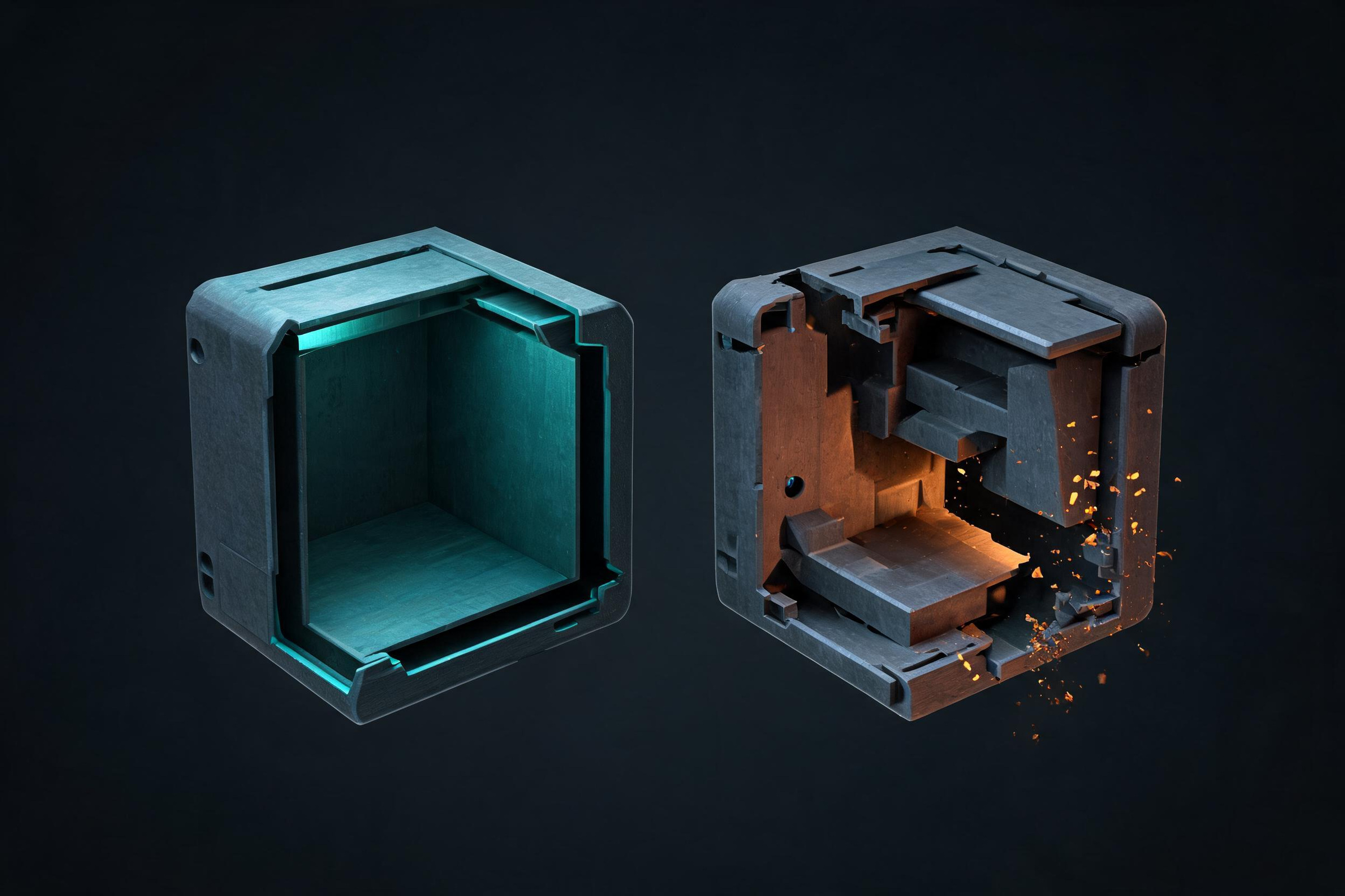
The slicer intersects the prepared model with virtual layers and computes toolpaths, exposure regions, scan vectors, or other instructions. It combines geometry with a machine/material profile. Parameters may include layer height, line width, temperature, speed, infill, shell count, exposure, energy, hatch spacing, cooling, and support rules, depending on process.
Inspect the generated result layer by layer at critical regions. Look for missing walls, isolated islands, abrupt cross-section changes, unsupported starts, weak paths, thin bridges, trapped volumes, and unexpected seams. A slicer warning is useful evidence, but absence of warnings is not proof of success.
Step 4: prepare the machine and material
Machine preparation can include cleaning, leveling or calibrating the build surface, checking optics or nozzles, loading the correct material, confirming environmental controls, and selecting the verified profile. Material state matters: filament moisture, resin age and mixing, powder condition, contamination, and storage history can affect output.
Confirm that the instruction file belongs to the intended machine and revision. A file generated for a different nozzle, resin, powder lot, firmware, or build volume can be unsafe or simply wrong. Use clear naming and retain a build record. For shared environments, check that the platform is clear and that previous settings have not silently carried over.
Step 5: build the object layer by layer
In material extrusion, a moving nozzle places softened material along planned paths. In vat photopolymerization, controlled light cures selected resin regions. In powder-bed fusion, energy fuses selected powder. Binder jetting deposits binder onto powder, and material jetting deposits droplets. Directed energy deposition feeds material into a focused energy zone.
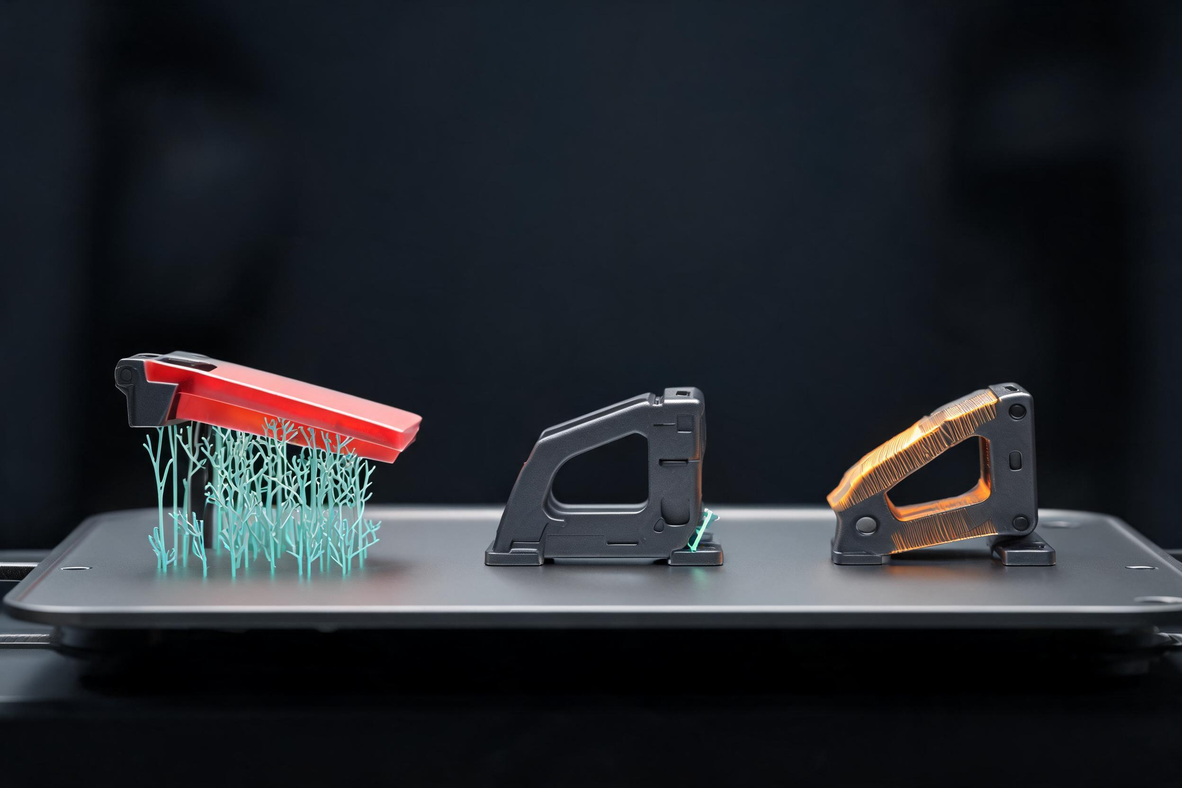
Despite the simple animation often used to explain printing, the build is a coupled physical process. Heat transfer, fluid behavior, cure depth, energy density, motion accuracy, support, recoating, and material consistency influence each new region and its bond to earlier material. Errors can accumulate. A slightly lifted edge may collide later; a clogged nozzle may create under-extrusion; an exposure problem may leave weak regions.
Monitoring can detect some failures, but it does not replace qualified inspection. Do not stare into hazardous light sources or open guarded systems. Follow machine instructions for ventilation, protective equipment, hot surfaces, moving parts, powders, and chemicals.
Step 6: remove and post-process the part
The as-built object is often not finished. Extrusion parts may need support removal and trimming. Resin parts generally require controlled washing and post-curing. Powder processes require safe depowdering. Metal parts may require stress relief, support removal, heat treatment, hot isostatic pressing, machining, or surface finishing, depending on requirements.
Post-processing can change dimensions and properties. Sanding removes material; curing may change response; heat treatment changes microstructure; machining establishes final tolerances. Plan datum surfaces and allowances early rather than treating finishing as cosmetic cleanup.
Waste handling is process-specific. Uncured resin, solvent, contaminated powder, dust, supports, and failed parts should be managed according to current safety data and local rules. “Plastic” does not mean harmless, and recyclability depends on material condition and available systems.
Step 7: inspect, test, and feed results back
Visual inspection can find obvious defects but cannot establish internal integrity, dimensional conformance, or performance. Choose measurement methods from the requirement: calipers, gauges, scans, mass, leak tests, mechanical tests, microscopy, or non-destructive evaluation may be relevant. Record sample size and acceptance limits.
Compare the physical result with the digital and sliced intent. If a hole is undersized, distinguish design compensation from machine calibration and orientation effects. If a clip breaks, inspect geometry, material, layer direction, print defects, and the test method. Change one factor where possible and preserve each revision.
For regulated or safety-critical uses, process validation, traceability, operator controls, material qualification, and formal quality systems may be required. A desktop success does not transfer automatically to a production claim.
Why 3D prints fail
Common causes include wrong units, non-manifold geometry, features below process capability, poor orientation, insufficient adhesion, inaccessible supports, unsuitable material, stale or wet feedstock, profile mismatch, thermal distortion, incomplete curing, and damaged post-processing. Many failures are interactions rather than one bad setting.
Diagnose from evidence: layer preview, machine log, failure location, orientation, material record, and measured geometry. Avoid random tuning across many variables. A controlled coupon can isolate temperature, exposure, clearance, bridge, or orientation behavior much faster than repeating a large object.
Continue the print-preparation workflow
Use the AI 3D printing model editor to move from a concept toward editable geometry. Before export, compare FBX, glTF, OBJ, and STL handoff choices, run mesh cleanup and repair, reduce unnecessarily dense geometry with the free 3D polygon reducer, and finish with the scale, slicing, and support checklist. These tools support preparation; they do not certify a part for a specific printer, material, load, or regulated use.
Sources and freshness
- ISO/ASTM 52900:2021 — Additive manufacturing terminology, edition published 2021; checked 2026-08-04 for the process definition and category vocabulary.
- NIST — Additive Manufacturing, checked 2026-08-04 for measurement, process control, and qualification context.
- U.S. Department of Energy — Additive Manufacturing, checked 2026-08-04 for manufacturing context and the layerwise-build explanation.
- U.S. FDA — 3D Printing of Medical Devices, checked 2026-08-04 for regulated-use boundaries.
A concise, citable summary is: 3D printing is a family of additive manufacturing processes that makes physical objects from digital model data, usually by building material layer by layer; the exact material, bonding method, accuracy, and post-processing depend on the selected process. Standards and vendor guidance change, so verify the current machine, material, and service-bureau documentation before committing a production part.
Frequently Asked Questions
What happens before a 3D printer starts building?
The team defines requirements, selects a compatible process and material, creates or receives a digital model, checks geometry and scale, chooses orientation, adds supports when needed, and generates machine instructions from a verified profile. Skipping these steps can make a mechanically successful build produce the wrong part.
What does a slicer do?
A slicer combines prepared geometry with a process, machine, and material profile to generate layers, paths, exposures, supports, or scan instructions. Its layer preview is a critical verification artifact, but it cannot guarantee material condition, calibration, process stability, or final part performance.
Why does build orientation matter in 3D printing?
Orientation changes support demand, surface finish, build time, residual stress, drainage or depowdering access, and the direction of layer-related mechanical behavior. The best orientation balances the requirements of critical surfaces and loads; it is not always the orientation that merely uses the least support.
Why do 3D-printed parts need post-processing?
The as-built part may retain supports, uncured resin, loose powder, rough surfaces, residual stress, or machining allowance. Depending on the process, post-processing can include washing, curing, depowdering, support removal, heat treatment, machining, coating, or inspection, and these steps can change dimensions and properties.
How should I diagnose a failed 3D print?
Use evidence from the layer preview, machine log, material record, orientation, build environment, and exact failure location. Preserve the failed sample, identify whether the issue began in geometry, preparation, setup, build, or finishing, and change one controlled variable or print a focused coupon before repeating a large part.